ARCH 655 Project 1
ArtScience Museum
 |
Choe, Jonathan. ArtScience Museum. 2021. Archigardener. https://www.archigardener.com/2020/12/artscience-museum.html. |
Architects: Moshe Safdie
Location: Singapore
Project Year: 2011
Typology: Museum
Art Science Museum Floor Plans
 |
| Safdie Architects. (2016b). Ground Floor. area. New Business Media Srl. Retrieved March 2024,from https://www.area-arch.it/en/artscience-museum/. |
 |
| Safdie Architects. (2016b). First Floor. area. New Business Media Srl. Retrieved March 2024, from https://www.area-arch.it/en/artscience-museum/. |
 |
| Safdie Architects. (2016b). Roof Plan. area. New Business Media Srl. Retrieved March 2024, from https://www.area-arch.it/en/artscience-museum/. |
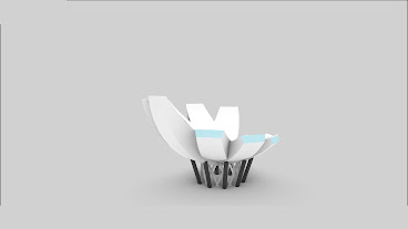
The ArtScience Museum is composed of 10 pedals that are inspired by a lily pad. The central atrium is a light and water feature that is a void space in the center of the rotated pedals. Many of the functions are housed underground with a small entry hall on level 1.
For this analysis we are looking to see the flow of water on the pedals of the
Art Science Museum Geometry
In order to understand how to remake the building we have to understand its geometry. The following images are taken from Safdie Architects' website showing the fundamentals of how these pedals were formed. They use a series of overlapping ellipsoids and spheres to create the inner and outer shapes of the pedals.
 |
| Safdie Architects. (2011a). Geometry of the ArtScience Museum. SafdieArchitects. Retrieved 2024, from https://www.safdiearchitects.com/projects/marina-bay-sands-artscience-museum. |
 |
| Safdie Architects. (2011b). Geometry of the ArtScience Museum. SafdieArchitects. Retrieved 2024, from https://www.safdiearchitects.com/projects/marina-bay-sands-artscience-museum. |
.jpg) |
| Safdie Architects. (2011c). Geometry of the ArtScience Museum. SafdieArchitects. Retrieved 2024, from https://www.safdiearchitects.com/projects/marina-bay-sands-artscience-museum. |
Lastly, a diagrid structure system creates the central atrium space which holds the mass of the flower above. The slanted columns are used to receive any lateral load from the curved structure above to prevent buckling. There are 10 foundational rotated about the center of the atrium at 36 degrees apart.
Project Design Intent
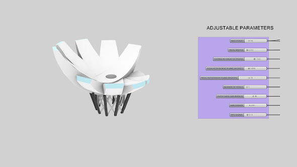
The ArtScience Museum is inspired by a Lilypad and flower. This building has 10 pedals which point to the sky to allow natural light to enter into the space through the use of skylights at each end with a central atrium where they conjoin. The aim of this project is not to only to recreate the pedals of the museum, but also control the size, number, angle of rotations, and add a Voronoi skin to the pedals. With the help of generative AI we can begin the investigation of how this building might look if we were to adjust for some of these changes.
Visualizing Through Generative AI
AI can be a helpful tool to begin to visualize many of the ideas that otherwise may take a long time to create through conventional modeling methods. Though, AI can be very hit and miss it is highly dependent on the users prompts when creating these images. For example, below are two images created using ChatGPT's DALL-E.
Original Photo Chat GPT
 | |
ArtScience Museum. (2024). About ArtScience Museum. ArtScience Museum Marina Bay Sands. ArtScience Museum. Retrieved March 2024, from https://www.marinabaysands.com/museum/about.html |
 |
| DALL-E Rendition |
The attempt was to recreate the ArtScience Museum with a Voronoi skin on the exterior in order to begin to visualize what this building could look like if the outside faces were not just simple white opaque walls. The prompt used here was "Add a Voronoi pattern to the pedals of this building while retailing its original shape and image for parametric modeling". Though this prompt is simply telling the AI to add a pattern, retain the building shape of the original building, and retain the original image for some parametric modeling ideas it isn't quite clear on a few key items; what is the subject and what should the Voronoi pattern look like. Below is an updated iteration using the same original image, however updating the prompt, and giving ChatGPT a reference image of a Voronoi pattern to use.
Reference Voronoi Pattern Chat GPT
With the updated prompt and a reference image we were able to get an image more in line with what we aim to create in this project. By giving more information in our prompt such as the location and name of the building in the original image we were able to utilize ChatGPT 4's fullest potential to search the internet for reference images. Therefore, making the image result resemble more the overall building and pull information for the Voronoi pattern based on our reference image. The prompt used to create this image is as follows: "Add a Vornoi Pattern to the ArtScience Museum in Singapore, retain original geometry of the building". Below are more sampled of AI images created through DALL-E that show both failed attempts and more successful attempts.
 |
| DALL-E Rendition Unsuccessful |
 |
| DALL-E Rendition Unsuccessful |
 |
| DALL-E Rendition Semi-Successful |
 |
| DALL-E Rendition Semi-Successful |
Project Modeling
 |
Choe, Jonathan. ArtScience Museum. 2021. Archigardener. https://www.archigardener.com/2020/12/artscience-museum.html. |
The following steps will be showing the process of recreating the original building through the use of grasshopper followed by different parametric solutions that relate to the AI generated imagery from the previous section.
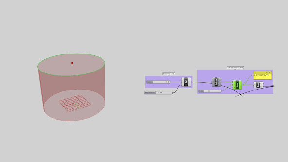
Step 1: Creating Cylindrical Base + Center Of Rotation
 |
| By creating a cylindrical base we can use it to help create the starting point of the buildings lower base and provide a center on which the pedals can rotate from. |
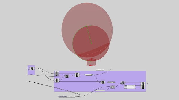
Step 2: Create Pedal Outer Shell
 |
| We then use the center of the cylinder to be the center of the sphere we create which will be used as the outer surface of the pedals. We use a subtraction component in the Z direction in order to create a small overlap between the cylinder and the sphere. This allows to make a parametric base height because the sphere is now tied to the height of the base (The Cylinder) no matter the height given. |
Step 3: Create Pedal Inner Shell
 |
| In order to create a secondary sphere that remains proportionate and parametric to the smaller sphere we must do two things; provide a location for the spheres center along a point on the smaller spheres surface and we must tie the scale of the larger inner sphere to the smaller outer shell sphere's size. By tying the bigger spheres radius to a scale factor of 1.5 times the outer shells size it keeps the two proportionate to one another as we change the size of the outer shell. |
Step 4: Subtract Inner Shell From Outer Shell
 |
| We then use the solid difference component to subtract the inner shell sphere from the outer shell sphere which gives us the result highlighted in green. |
Step 5: Create Ellipsoid to Intersect With
 |
| The next step is to create an ellipsoid shape to overlap with the result from inner shell outer shell subtraction. This The ellipsoid geometry is a scaled variant of the outer shell sphere using the Scale Non-Uniform component. It will then allow us to create a parameter that can control the width of the pedals because it uses the original sphere of the outer shell. We then plug in the two components into the Solid Intersection component giving use the base C-shaped Pedal. |
Step 6: Removing Ends of Pedal For Skylights
 |
| In order to remove the pointed ends of the C-Shaped resulted intersection we create a series of concentric contours along its inner surface and extrude them in order to use the Solid Difference Component to remove both ends. This is done to create the flat surfaces at each end used for the buildings skylight system. As the outer shell scales we must keep the number of contours proportionate to its size so we always remove the same size ends of the C-Shaped Pedal. This is done by tying the outer shell spheres size into a divide component where the result goes into the contour distance. This ties the size of the outer shell to a proportionate distance of contours. |
Step 7: Rotating Pedals Around Center
Step 7A: Rotating Pedals XZ-Plane
 |
| This step is the most crucial step as the pedals rotate in multiple directions. The pedals rotate in elevation around the center of the sphere in the XZ-Plane and then rotate in plan around the center of the cylinder in the XY-Plane. In order to do this parametrically we must create a series of rotations in the XZ plane first. Using the Rotate component and plugging in a Series component into the angles, we can create a list of rotate geometries in the XZ direction. |
Step 7B: Rotating Pedals XY-Plane
length in the XY-Direction. By plugging in another series into a secondary rotation we can
then use the same number of pedals plugged into the first Series component. This will
ensure that our lists stay the same size so that each rotation rotated happens per pedal.
Step 7C: Creating Atrium + Applying Material to Pedals
 |
| Once the pedal rotations are complete we can Solid Difference a cylinder from the center to create the atrium of the building. Then plugin the difference into a Deconstruct Brep in order to get the list of faces so that we can apply a material to. |
Step 8: Creating Building Base Diagrid Structure
Step 8A: Create a Series of Circles and Points
 |
| In order to create a diagrid structure, we must create a series of circles by taking the original top curve of the base cylinder and making copies at a set distance and dividing them. In order to do that we must use the Deconstruct Brep on the original cylinder and take the edges plug them into a List Item and select the upper edge. This edge moved downward in the Z direction several times. Using the Move component we plug in a series component tied to the height of the base divided by 3 with 5 circles. This gives us a proportionate distance based on the base height. Finally these circles are divided to give us the points on the circles to connect. |
Step 8B: Connect Points and Pipe Structure
 |
| Once we get all the points on the circles we can then begin to connect each point. To create a diagrid we must shift the list of points at each concentric circle to get a diagonal path. To do that we must take the list of points and plug them into Shift List component and use a Modulus component that is tied to the number of divisions we create. The second set of numbers plugged into the modulus is a Range given to use by the number of circles minus one. Once these are plugged in the shift list will be flipped and we will Interpolate Curve on the list of points giving us the lines for the diagrid. Those will then be plugged into the Pipe component and given a radius to make the structure. |
Step 9: Creating Building Base Angular Columns
 |
| Once we create the diagrid we can use the list Item component to select the upper and lower circles of the series of circles. After selecting the upper circle we must scale it up in order to make the angled base columns. Then divide the lower circles and upper circle by the same number of points as the diagrid. We then connect lines from the lower and upper points in order to get the line we will use to connect to a Sweep component using a rectangular section profile. |
Step 10: Combining Base + Building Mass
 |
| After the Base has been modeled we can turn the materials for the Pedals Mass back on and apply the same Material component and previews to the base diagrid structure and angled columns. |
Adding Voronoi Skin
 |
| In order to add a Voronoi skin to the outside surface we must use Deconstruct Brep to select the exterior shell face of the pedals using the List Item Component. Next we populate the surface with a number of points and use those points to populate the Voronoi 3D component. By plugging in a Bounding Box into the Voronoi 3D using the Surfaces we can make sure the voronoi pattern is applied to the entire surface within the bounding box. Lastly, we use the Breo|Brep component to get the curves of the Brep to Pipe giving us the Voronoi pattern on the outside surface. To get the frame of the surface piped we can use the list item to select the 4 outside edges of the surface and plug those into the pipe component as well. |
Full Grasshopper Script
Curved Surface Analysis
Water Flow Analysis
For this analysis we are looking to see the flow of water on the pedals of the
building. The ArtScience Museum uses the curved surfaces to funnel water
into the central atrium in order to create a water feature when it rains that
will filter into the pool of water surrounding the flower. Using the Deconstruct
Brep on the rotated pedals we can use a List Item to select the upper surface
used to simulate the water flow. We will then subdivide the surface into a set
number of points to sample for this analysis. Those points are fed into a loop
where we can select the number of samples to run. In this case we choose 80
samples to run so that we can see all the points move as far as they can in the
simulation. We use the Move component to give it a direction, in this case Unit Z,
to simulate gravity giving us the simulated movement of each point.


Comments
Post a Comment